~harmonic tremolo~
video demo
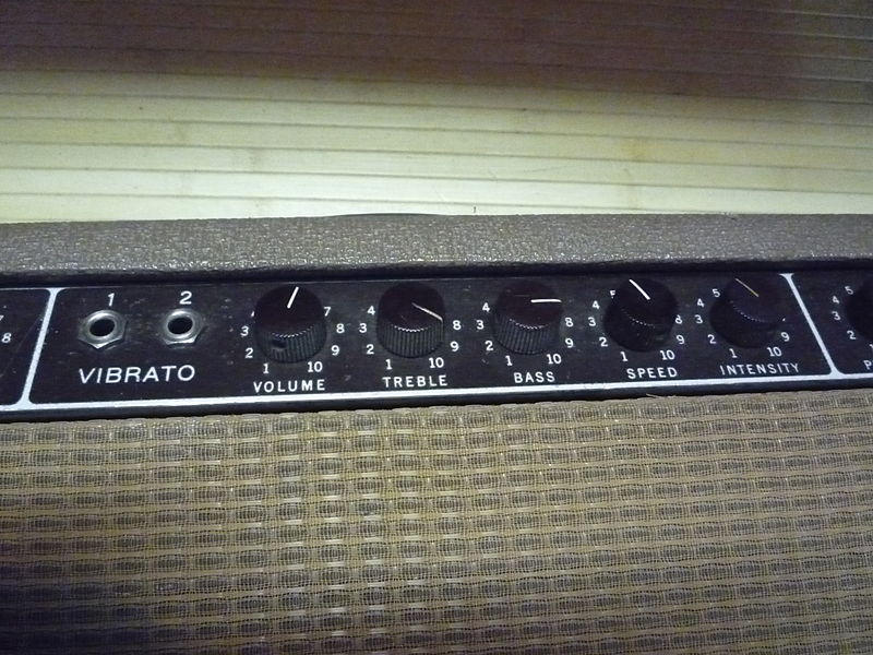
this circuit is modeled after the tremolo circuit in the pre-CBS fender bandmaster, which i believe was designed to emulate a leslie cabinet. while traditional tremolos modulate the amplitude of the entire audio signal evenly, the tremolo circuit in these amplifiers splits the input into two bands (low and high and high frequencies with a crossover at around 400Hz). the bandmaster uses a control signal to alternate the output between these two passbands. this creates a "wah" type effect when trading between low and high frequencies.
here i will describe (to the best of my ability) how this circuit works.
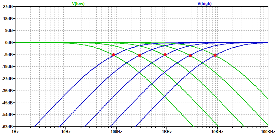
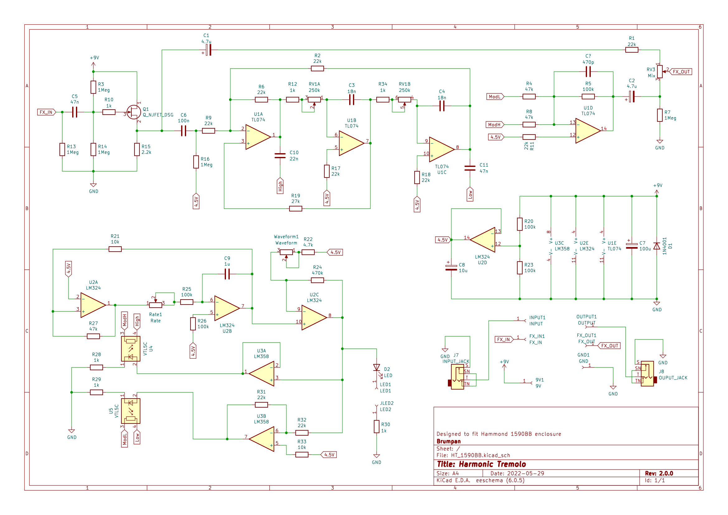
looking at fig. 1: the circuit begins with a jfet input stage to provide high input impedance. the following filter stage is comprised of a state-variable filter. the filter sends both a high-passband and a low-passband to the next stage. a dual gang logarithmic potentiometer controls the resistors leading to the integrators in the state-variable filter (U1B and U1C). these resistors along with the capacitors determine the crossover frequency. using the formula 1/(2*pi*R*C) the range of the crossover frequency is calculated to be between 35Hz-8.8kHz which is more than enough to encompass the range of a guitar amplifier. fig. 3 shows the frequency response of the filter for a few arbitrary settings.

fig. 2 - state-variable filter frequency response
the next stage involves vactrols. for each vactrol i used an ldr and a red led, i used a hot-glue gun to fasten them together, then covered their bodies with black, glue-lined heatshrink. Rod Elliot at esp has a great article on vactrols and was a great help, you can find it here. a vactrol is essentially an optoisolator. when current flows through the led and it illuminates, the ldr (light dependent resistor) decreases it's resistance. when i tested my ldr's they varied from 2.2Mohms in complete darkness to around 100 ohms with the led fully illuminated. in my circuit, high and low frequency components of the filter stage are fed through seperate vactrols and into the summing amplifier output stage.

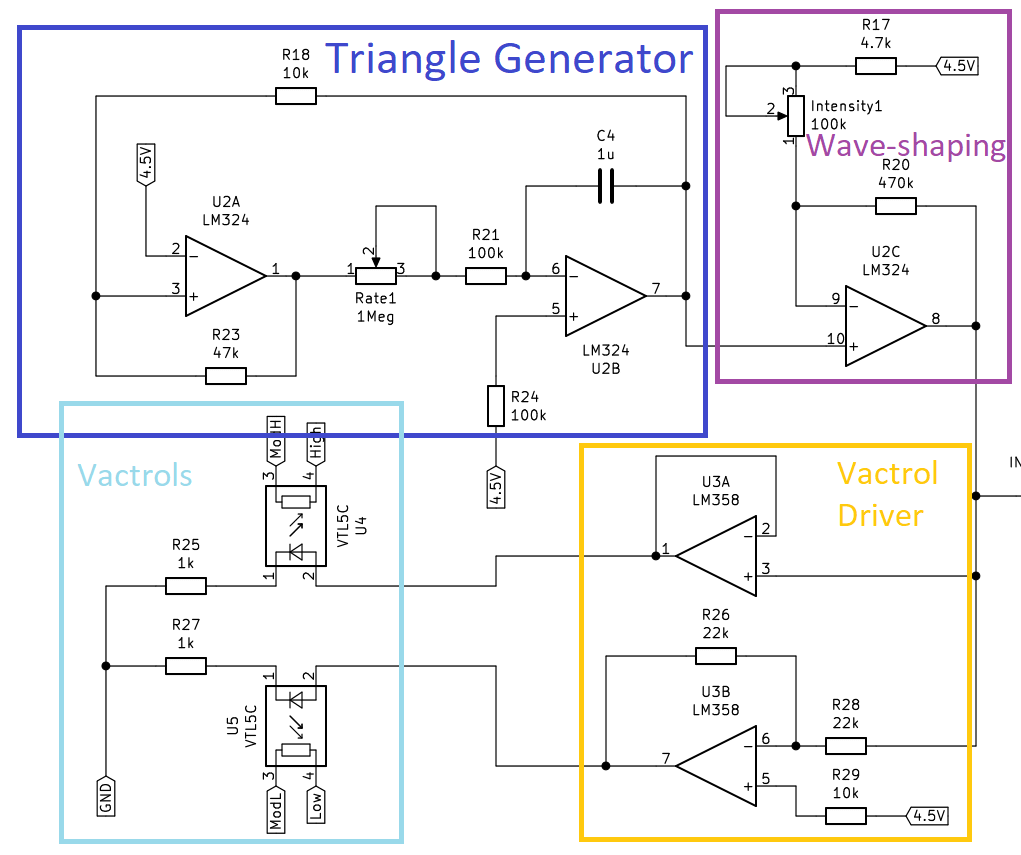
fig. 3 - oscillator/vactrol section
to control the vactrols, a triangle waveform oscillator using two op-amps is used (U2A and U2B). this triangle waveform is then sent to a non-inverting op-amp (U2C) with variable gain controlled by a 100k potentiometer. the gain of this stage is adjustable between 5 and 100. with a gain of 5, the output of the triangle waveform is brought right up to the pont of saturation. when the gain is set to 100, the waveform is fully saturated and resembles a square wave. this can be seen in fig. 5.

fig. 4 - output from oscillator amplifier
in short, the slope of the waveform that controls the vactrols translates to how quickly the volume at the output is clamped. the square control signal sounds more abrupt, while the triangle waveform has a softer transition between the high and low frequency signals. the control signals are sent to a dual op-amp, where one channel is inverted. at this point each vactrol is controlled by equal and opposite signals.
finally, the output of the vactrols are connected to a summing amplifier with a gain value of -2. this is to correct the loading between the input stage and filter stage. it also inverts the signal to correct the phase since the state-variable filter has a gain of -1.

fig. 5 - input signal (100Hz and 5kHz at 2Vpp)

fig. 6 - output signal (vactrol oscillator set around 3Hz, waveform gain set around 50%)
i made the pcb in KiCad and sent out to JLCPCB to have it manufactured. i designed the board to fit perfectly inside a Hammond 1590BB enclosure.


